(c) 1999,2025 Peter McCollum
The RS-6 HF Transceiver
The RS-6 was intended as a replacement for the wartime SSTR-1 set. Functionally, it is a miniaturized version of the RS-1, but without the requirement to be waterproof for burial. It has a very similar design, but uses sub-miniature tubes in the receiver and power supply regulator, and a miniature tube as the transmit oscillator. Physically, the complete radio is in four units: receiver, transmitter, power supply, and power supply filter unit (which also provides storage for some accessories). The power supply uses a 6X4 tube instead of the selenium rectifiers used in the RP-1; presumably because the selenium units in the RP-1 are too bulky (they require more than twice the space of a 6X4). Since the unit is built as 4 pieces, rather than 3, there may have been a requirement that each piece was no larger than a certain size.
The RT-6 tunes 3-16.5 MC in two bands with up to 10 watts output. Maximum keying speeds are 40 WPM with the built-in key or an external hand key (in either case using the internal keying relay), or 60 WPM with an automated keyer that drives the tube cathodes directly. The RR-6 tunes 3-15 MC in two bands, with either VFO or crystal control. The receiver also has a BFO and a crystal calibrator. The power supply operates from 70 to 270 VAC, 42-400 cycles, or from 6 volts DC. Each of the four main units is stored in a plasticized cloth bag, plus an additional bag for accessories.
There also is an RS-6A [ref 116], which includes the RT-6A and RR-6A. The only significant difference is that the RS-6A tunes 4.5-22 MC, whereas the RS-6 tunes 3-16.5 MC. There are also some minor circuit differences, and the RT-6A uses a 6AK6 oscillator instead of a 6AG5.
RS-6 Radio Station Specifications |
|
|
|
|
Receiver RR-6 |
Transmitter RT-6 |
Power Supply RP-6 and RA-6 |
Weight |
3 lb 2 oz |
2 lb 14 oz |
RP-6: 5 lb 11 oz RA-6: 3 lb 11 oz |
Dimensions |
6-3/4" X 5" X 2-1/4" |
6-3/4" X 5" X 2-3/32" |
RP-6: 8-1/16" X 4" X 2-3/16" RA-6: 8-1/16" X 4" X 2" |
Tube complement |
5899 RF amp |
6AG5 oscillator (6AK6 in RT-6A) |
6X4 rectifier |
|
5899 mixer |
2E26 final |
|
|
5899 oscillator |
|
|
|
5899 IF amp (two) |
|
|
|
5718 detector |
|
|
|
5718 audio/cal. osc. |
|
|
|
5718 BFO & bias |
|
|
Frequency Bands |
3-6.5, 6.5-15 MC |
3-7, 7-16.5 MC |
|
Power Output |
|
6-10 watts |
|
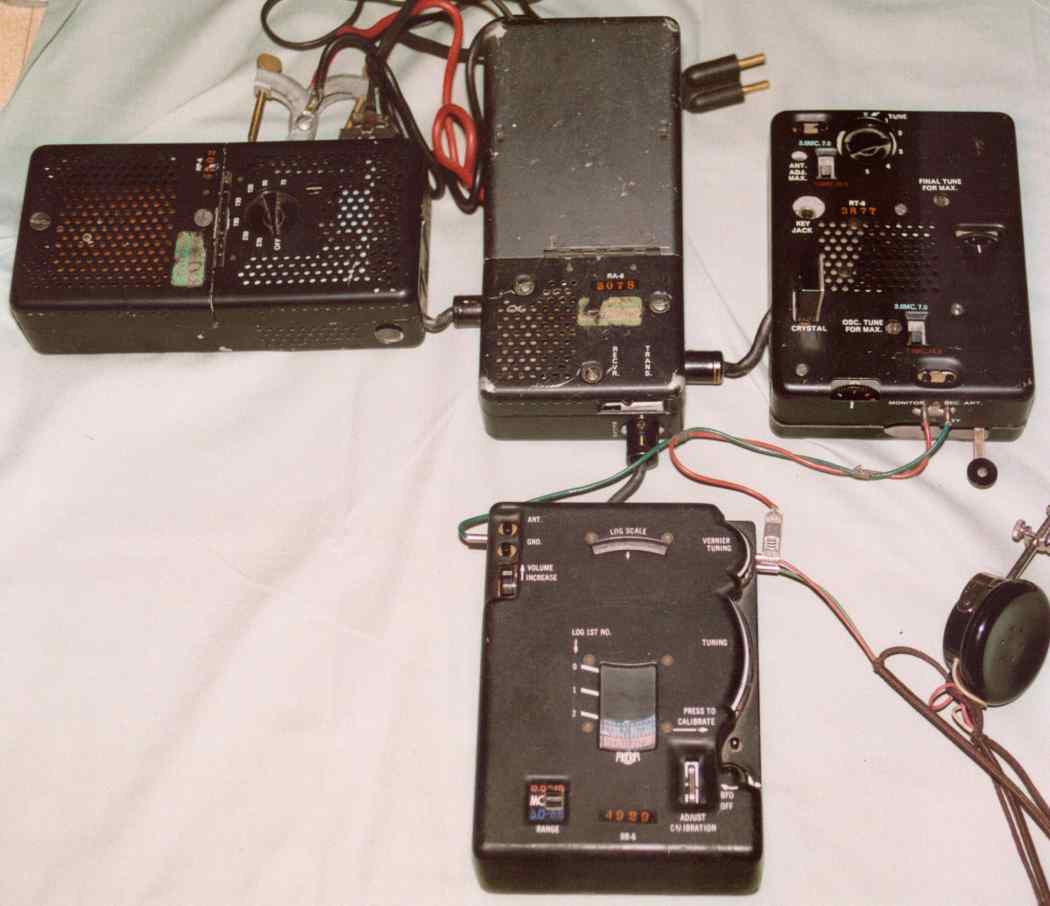
A complete RS-6 station ready for use from AC mains power. Note the many cables and connectors – a total of 10 cable-ends must be connected (including antenna and ground, which are not shown in the picture).
The RT-6 transmitter, shown with the key extended, and the RR-6 receiver.
Development History
The RS-6 started to be available in the field in late 1951 or early 1952 [ref 125, ref 104], but was under development before February 1950 [ref 107], and lab models and specifications were complete in September 1950 [ref OC History, chapter II]. An early unit appears to have component date codes in 1951. Most other units have codes for 1952 and 1953. A memo indicates that “production flow” of RS-6 sets was due to start by Sept. 1952 – this may be referring to full production, as opposed to prototype/initial production. By observation of markings in the RR-6 receiver, the IF transformers are marked with a number such as "119-3-25" - the "3" represents 1953, and the "25" is a week number for that year (the '119' is an EIA manufacturer's code, representing Automatic Manufacturing Corp., a major maker of IF transformers at that time). The Manual Addendum is dated May 1953, and mentions serial numbers up to 2614 with certain hardware differences. All RS-6 production appears to have been completed in 1954. Declassified documents continue to name the RS-6 in operations until at least 1962 [ref 102].
The contractor for RS-6 and RS-6A sets was Motorola in Chicago. The first 500 units, delivered by Nov. 1951, were designated “RS-6X”, but were not satisfactory according to specification No. 50-A-1006A. The total contract was for 5425 sets at that time. Various problems were negotiated between CIA and Motorola, and “production-ready” units were received in April 1952. In June 1952, the Air Force became interested in the set, and asked the Agency to procure 1500 units for them. The first 100 of these sets were delivered from the group of 500 RS-6X prototypes. The AF request caused the total contract quantity to be increased to 6500. The first 25 final production units were received Oct. 1952. RS-6A first prototypes were being evaluated in March 1953; volume production of 2500 units started about June 1954. Meanwhile, an August 1954 memo states that “Test & Evaluation Section” had never received units 7998 through 8000 on contract PSC-148-UNV. So it appears that RS-6 (non-A) production stopped at 8000.
Based on the above information, combined with observed serial numbers, a large number of RS-6 sets were manufactured – up to about 10,000 sets of RS-6 and RS-6A combined. Overall RS-6 components are known to number from 33 up to over 10,400. The RT-6 and RR-6 units are seen in the range up to 8000, while RT-6A and RR-6A units cover the 8000-10000 range, and RP-6 and RA-6 cover the entire range of numbers (there is no RA-6A or RP-6A). So it appears that RS-6A manufacturing continued the numbering where the RS-6 left off – the numbers were not reset to "0" when the "A" model was introduced.
In August 1962 a PS-13 rechargeable power supply was being developed.
In May 1967, the CIA discussed how to dispose of RS-6/6A inventory, with the following historical background given:
[Redacted] reviewed the history of the RS-6 and the requirements for which it was designed and procured; circa 1949-1951. The set was built as a manual keying, low-cost, and light-weight replacement for the World War II SSTR-1. At the time, Agency plans focused on large scale stay-behind activities and strategic reserve/war planning programs. However, world conditions did not require implementation of contingency plans and as a result RS-6 equipments were not used at the anticipated rate. Another factor that has had a bearing on limited use of RS-6 equipments was technical advancements made in the development of clandestine radio systems starting about 1957-58. The advent of transistors, medium speed keying [burst-coders], and improved electronic packaging techniques allowed development of more reliable and sophisticated agent radios. While, over the years, RS-6’s have been used where practical, no significant inventory reduction has been possible. Changing operational concepts coupled with technical advancements have rendered the RS-6 obsolete in all respects. It was noted that newer equipments are available to replace RS-6 sets in strategic reserve if such action is necessary.
[The memo then mentions that “The Air Force has long since discarded the RS-6’s they purchased a number of years ago.” The Agency considered disposing of the sets through a surplus sale, but noted “A further potential embarrassment that could result from sale as surplus would be the possible availability to {redacted} at a price of $25 to $50 of a radio set for which they had paid approximately $450.00”. The decision was made to destroy the sets.]
One of the replacements for the RS-6 in field use was the AS-3 set. The transition to the AS-3 was occurring in 1962 [ref 102]. Back in late 1952, when the RS-6 was first being introduced in some teams, it was anticipated to be an improvement over the RS-1 because of the weight difference. A report from that time complains that the RS-6 and RS-1 have “indelible markings”, making it difficult to sterilize [ref 105]. Another report describes how external markings were changed to Russian:
“The few articles of American manufacture that were provided were sterilized; even the radio equipment had the English markings removed and Russian equivalents stenciled on (this was done only in the hopes of deceiving a militiaman making a spot check for black market goods; upon close examination all the COMMO gear can easily be proven to be of American manufacture).” [ref 114].
Many RS-6 components are found with a green and white “acceptance” sticker attached. Previously, I had believed that the sticker was only found on units that had been purchased by SAC. However, some sets that have the sticker are clearly CIA sets, including a set that was part of a stay-behind package in Austria (described in the “Other Information” section, below). Several CIA documents refer to Final Inspection being performed by the U.S. Navy – it seems likely that the stickers originated there, but it is unknown if ALL sets passed through that process.
Download documents here:
RS-6 and RS-6A Manual (no figures or schematics)
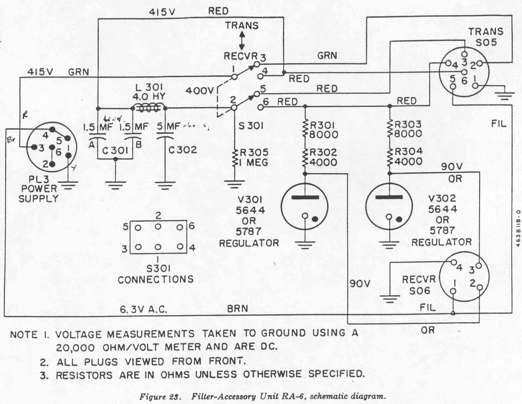
Filter/accessory unit RA-6 schematic
The RS-6XX Variant
Another variation is the RS-6XX set. CIA memos indicate that it was a “modified” design to address issues with spurious radiations that could be heard in a nearby household radio. The biggest differences were to eliminate the capability for break-in keying and sidetone. A separate User Manual was produced for the “XX” sets. These sets were available in April 1952.
Download the RS-6XX manual here
[The following “Preliminary” manual does not mention the “XX” variant, but the description and schematics are mostly (not entirely) from the “XX”, including the lack of break-in and sidetone.]
Differences noted in the “XX” equipment:
· RR-6XX: The cathode circuit of the detector (V6) is different, and the AGC signal no longer drives the detector grid. The 1st and 2nd IF cathode resistors are a different value.
· RT-6XX: Parts associated with the keying relay, sidetone oscillator, and receiver antenna connection have been removed. The external key jack is 2-contact, instead of 3-contact. The 2E26 power amp is no longer keyed – the cathode resistor is tied directly to ground. Only the oscillator is keyed. Capacitor C119 on the 2E26 plate circuit has been removed. The final neon tuning lamp is now connected via a small capacitor, instead of a ‘gimmick’ wire.
· RA-6XX: C302, the large oil capacitor inside the storage compartment is a smaller dual 1.5 uF unit, instead of a single 5 uF unit. NOTE: An example “XX” unit was apparently modified from an early RA-6 unit, and shows the following manual changes to the markings: In the hookup diagram on the inside of the lid, the hand generator is marked "GN-58 or SSP-11" instead of just "GN-58". The diagram does not include the sidetone connection between the xmtr and rcvr. Also, someone has used 'white-out' to remove the receiver antenna connections from the diagram. [Note: The SSP-11 is described in the RS-1 manual as a "modified GN-58". The SSP-x designations originated with SSTR-1 power supplies during WWII. This implies that the OSS used a modified GN-58 with one or more radio sets, and that these generators were still found in the field during the time of the RS-6.]
· RP-6XX: C206 has been removed; C205 is a different value.
The unit on the right is an “RT-6XX” unit. The “XX” model has no provision for the "monitor" connector or the "rec. ant." connector.
Part of the diagram inside of an RA-6XX. Note the mention of the SSP-11 generator; and white paint has been used to remove the sidetone cable from the diagram. Note the mention of the “SSP-11” generator.
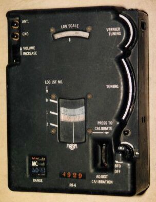
An RR-6 with the "XX" marking. Note that the "XX" is marked differently with a stencil; probably not as part of the regular manufacturing process. Another identifier is the white calibration marks directly below the dial window – on the “XX” units, this marking is about twice as wide. Compare with the picture below of a standard RR-6. Known “XX” units have low serial numbers, and are very rare. See [ref 124] for a mention of the RS-6XX set as part of an agent's equipment in Sep. 1953. Image courtesy of Dennis Monticelli.
Other Information
Evidence of CIA use of the RS-6 includes remarks from retired CIA Commo officers; and a variety of declassified documents. An example is found in [ref 126], regarding a member of a stay-behind net in Germany, who was discontinued because he was a security risk:
"KIBITZ-171 was a W/T instructor in the KIBITZ-15 Net from October 1951 until June 1952. [...] Prior to his employment as a fulltime W/T instructor for KIBITZ, subject was employed by Rhine Military Post, Kaiserslautern in the Signal Section. [...] KIBITZ-171 knows the following: W/T Operational Data: DYCLAIM W/T procedure and training methods. (He has instructed some 14 W/T agents in the KIBITZ-15 Net.) He is familiar with TR-1, RS-6, RS-1, Bud Oscillator, AdK, MP-1 SX-71, Hallicrafter, crypto system and signal plan system. NOTE: All equipment that was used by KIBITZ-171 in his duties as instructor, has been taken away from him."
A complete RS-6 set including crypto pads and German documentation was found in Austria, and sold on eBay in 2014. The serial numbers of the units indicate that it was issued to agent “GRBLAMED-31”, for project GRCROOND, in June 1961 [ref 118, ref 119]. GRCROOND was the master para-military program for Austria, and included at least 6 sub-projects (including GRBLAMED) initiated in 1960.
The RS-6 is not a very "user-friendly" design - too many cables and wires, with the possibility of hooking things up wrong, and exposed high voltages on male connector pins (the manual warns of the hazard!). The sidetone connection between the transmitter and receiver seems to be an afterthought: an alligator clip is used to connect to one of the pin plugs on the earphone. For some missions in 1952 and 1953, the CIA mitigated the problem by delivering RS-6 sets attached to a board, with the various connections already in place [ref 113]. The manual also discusses a situation with the keying relay that requires the operator to press the key when changing modes, etc. - it would seem that there are many opportunities for error.
Very little field maintenance is possible. Apparently, miniaturization was a priority in the design, and this was accomplished at the expense of ease-of-use. And, there may have been a design requirement that no single part of the set would be larger than a certain size; therefore the power supply was designed as two units.
The RS-511 (the "Attache Case Radio" shown in Keith Melton's books) is based on RS-6 components mounted on a panel that mounts in a briefcase.
RS-6 Usage by the Air Force
The RS-6 is known to have been on-board equipment in the following aircraft: B/RB-47E, B-47 ECM, and B/RB-52. A SAC manual [Manual 64-1, see Ref. 15] has been seen which specifically lists the RS-6 as required equipment during certain types of missions. It is listed as "Radio kit, long range, type RS-6". The contents of the kit include a nylon container (NOT the same as the bags for the individual RS-6 components - see picture, below), and a GN-58 generator (the manual says "GN-68", but that is presumed to be a misprint). [The information in this paragraph is courtesy of Danny Cahn.]
One story is that RS-6's were mounted on the bottom of B-47 ejection seats, and that the crew would use them to call for a pick-up after they had released nuclear weapons on a Soviet target. This would be needed because a B-47 wouldn't have enough range to hit the USSR and return, so it would have to ditch on the way back home.
The RP-6 power supply unit. Note the AC voltage selector switch. An alternate power source in the field was an FC-96-M NiCd battery [ref 116].
The RA-6 Filter-Accessory unit, with the lid open. Visible are the AC power plug, and the red and black DC power cables with battery clamps.
Comparing the RS-6 Design to RS-1
Because of the design similarities with the RS-1, it is possible that the RS-6 was designed with involvement from RDR Corp., and then manufactured by Motorola. Some of the design similarities between the RS-1 and RS-6:
o The AC power cords/plugs are an interesting design, and are identical on both sets. Obviously the same design specification was used, and probably the same sub-contractor.
o Both power supplies feature a switch for selecting the AC input voltage, and a method for determining the correct setting (meter and neon lamp). There are several voltage selections, not just 115/230 volt settings.
o Both receivers use a constantly-running BFO oscillator, which is rectified by a diode to provide grid bias. When the BFO is "off", the oscillator is running at a higher frequency, to make the beat note inaudible.
o Both receivers control the gain via a pot and the negative bias from the BFO, to control the RF and IF gain - there is no gain control on the audio stage.
o Both transmitters have one oscillator tube driving a 2E26. The designs of the two transmitters are extremely similar; including a modified Pierce oscillator circuit.
o Both transmitters use two neon lamps for tuning, plus a #47 bulb (#49 for the RS-6) as an antenna current indicator.
A SAC RS-6 bag. Image courtesy of Danny Cahn.
The instruction cards included with the RS-6 set. Image courtesy of Dennis Monticelli.
Comments from Jess Guarderrama:
I was a radio operator (CW) with the 24th Division LRRP from 1960 to 1963. We used the RS-6 on all of our field operations. We could load just about anything. I remember one operation when I ran a wire along side of a laundry line and maintained contact with our base station throughout the entire operation. The transmitter was easy to load and the receiver was unbelievable when it came to picking the base station signal out of the noise. I remember using this rig to operate on the ham bands during some of the field operation (DL4TU was my call then). I ran many a commo check cranking the GN-58 generator with my right hand and sending with my left hand while the key was strapped to my left thigh.
Regarding RS-6 parts, for persons wanting to have authentic-looking accessories:
· The battery clamps are Mueller "ClamPipe" #58, with flat thumb screws.
· The alligator clip on the accessory cord is a Mueller #45.
· The wires on the accessory cord are a twisted pair of dark red and dark green, with black string-ties.
· The 'hank antenna' is just a 100-foot bundle of Air Force-gray wire rolled around a rectangular piece of cardboard.


